
Industrial dry cooler
Hyper QXchanger™
Industrial dry cooler.
An induced-draft dry cooler for hyperscale and AI campuses. One module design on every job; the array is engineered to your site.
01 / AIRFLOW
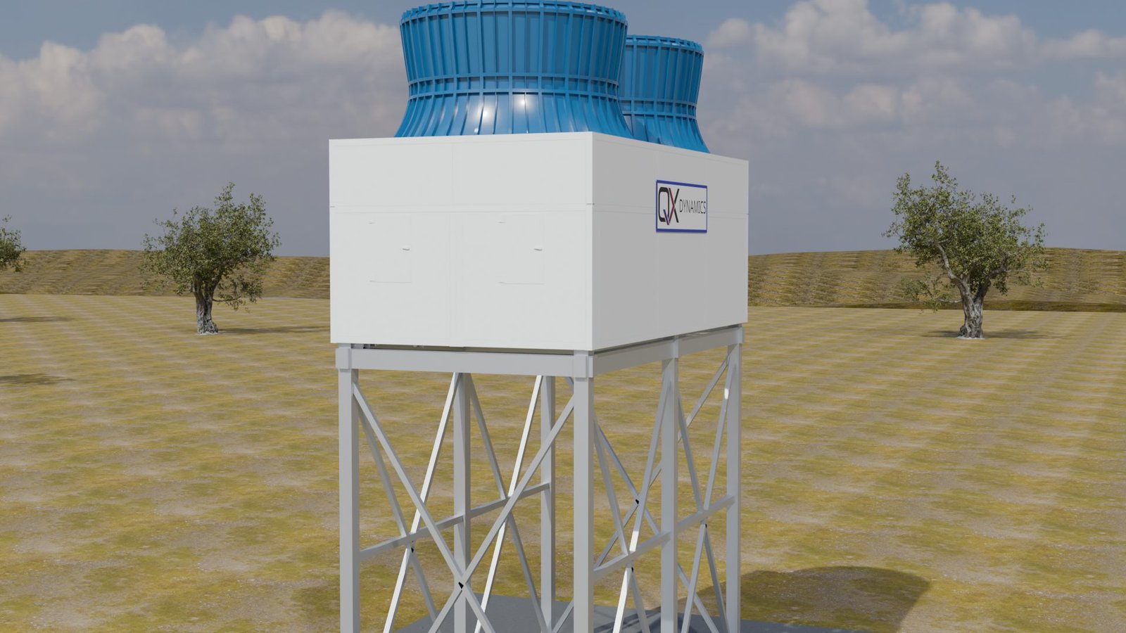
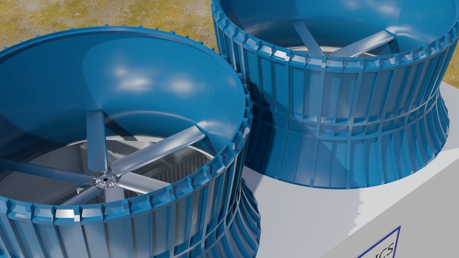
Two fans, shrouded stacks.
Induced draft: two large-diameter axial fans pull ambient air up through the coil banks and discharge it vertically. Low speed keeps tip speed and noise down. A VFD on every fan.
02 / COIL SERVICE
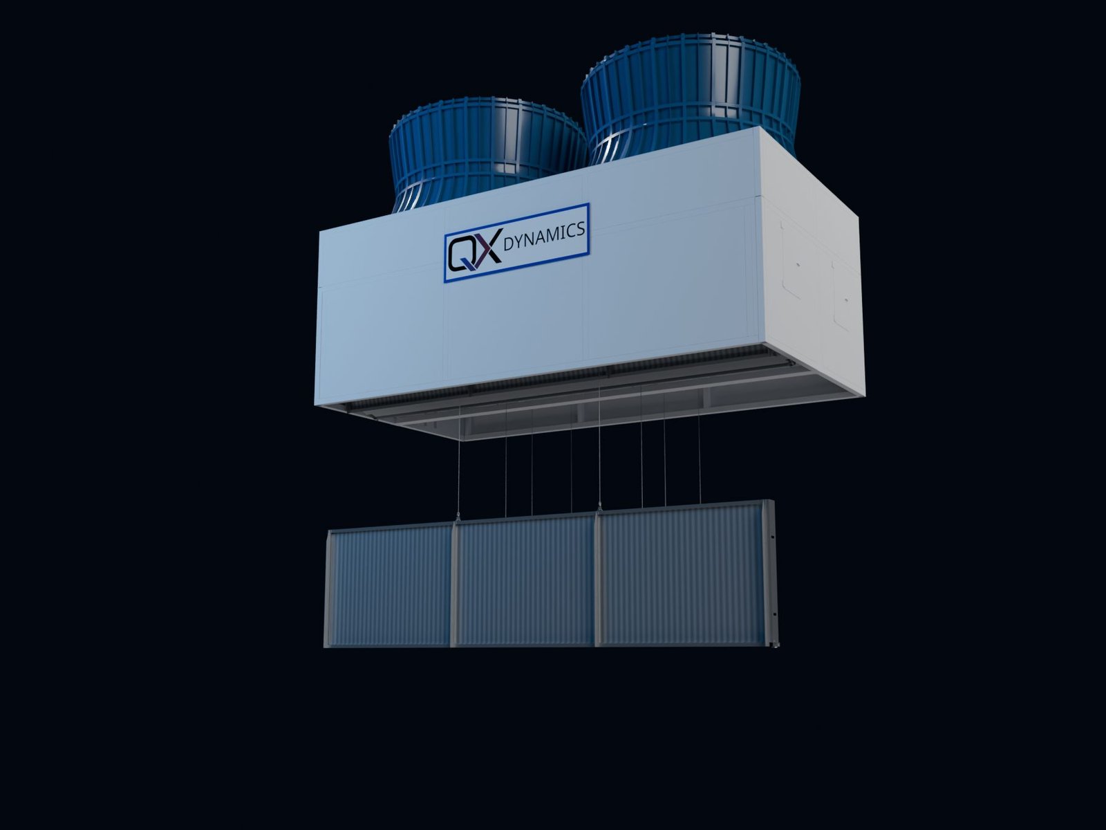
Coil banks lower out the bottom.
Each coil bank comes straight down out of the casing on preplanned rigging and equipment, for cleaning, inspection or replacement.
03 / INSIDE
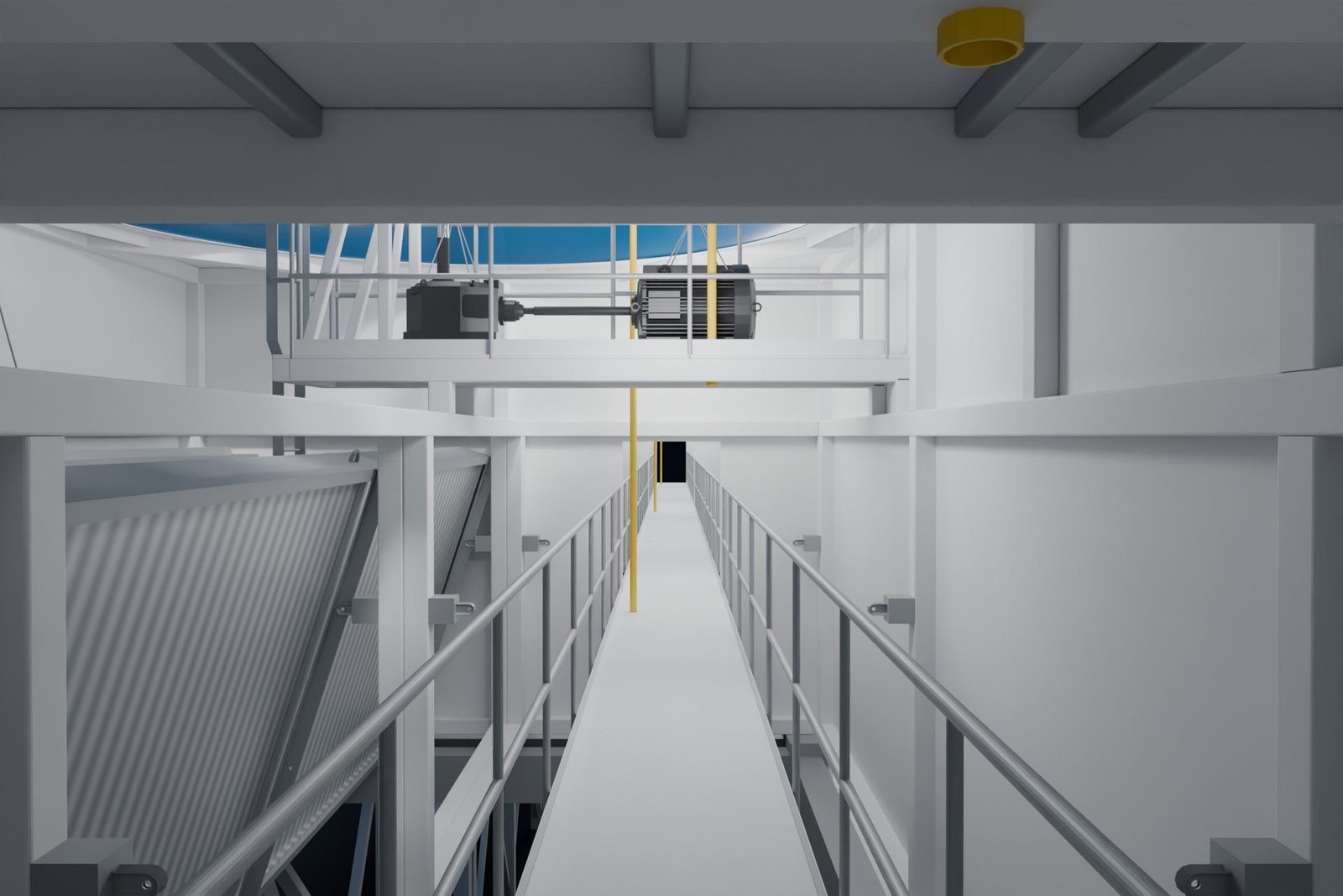
Service from inside the module.
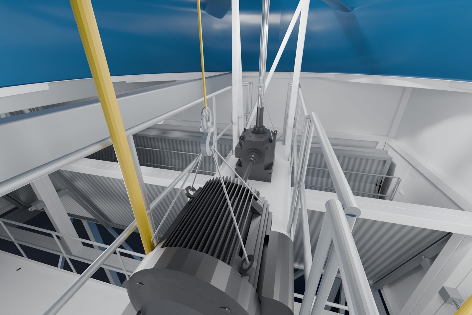
A walkway runs the length of the module, with access up to the fan deck, motors and drives.
04 / MOTOR CHANGE-OUT
Motors come out on a portable hoist.
Lifted off its base, turned and run out along the hoist rail, lowered to the walkway, then wheeled out the end door onto the catwalk.
05 / ACCESS
Down to grade from the catwalk.
A davit crane on the catwalk landing lowers the motor to grade. Stairs and a catwalk along the end of the array give maintenance access.
- Type
- Induced draft
- Fans
- 2 per module, VFD each
- Fluid
- Water or PG, closed loop
- Water use
- None
Why dry
No make-up water.
No treatment program.
A dry cooler rejects heat by sensible transfer alone. Nothing evaporates, so there's no make-up water to buy, no chemical treatment, no blowdown, no drift, no visible plume and no Legionella program to run.
AI + hyperscale
Campus-scale heat rejection for large chilled-water and process loops.
Water-constrained sites
Where water rights, cost or permitting rule out evaporative towers.
Warm-water loops
Liquid-cooling plants that run warm enough to reject straight to ambient.
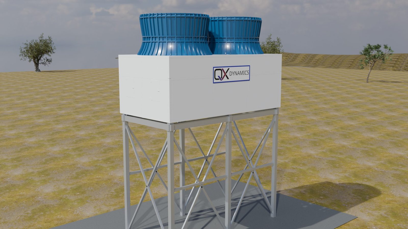
Design
Induced draft,
large low-speed fans.
Each module draws ambient air up through its coil banks and out through two large-diameter axial fans in shrouded stacks. Low rotational speed keeps tip speed and noise down.
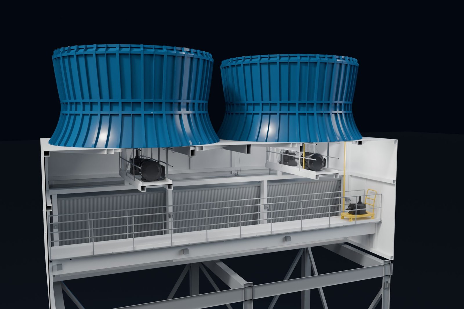
Induced draft
Fans sit downstream of the coils and pull ambient air up through them, then discharge it vertically through the stacks.
A VFD on every fan
Each fan has its own variable-frequency drive, so capacity follows the load and the weather.
Fan inflow checked with CFD
Inflow uniformity at the fan was analysed with CFD and blade loading checked against it.
One module, every job
Every module is built to the same design. What changes per project is the array around it.
Service
Service access
from inside the module.
Coil banks lower out of the casing with preplanned rigging and equipment. Inside, a walkway runs the length of the module to the fan deck, motors and drives.
- ◆Coil banks lower with preplanned rigging and equipment for cleaning, inspection or replacement
- ◆Internal walkway and ladder to the fan deck
- ◆Sections sized for standard over-the-road transport
Recirculation
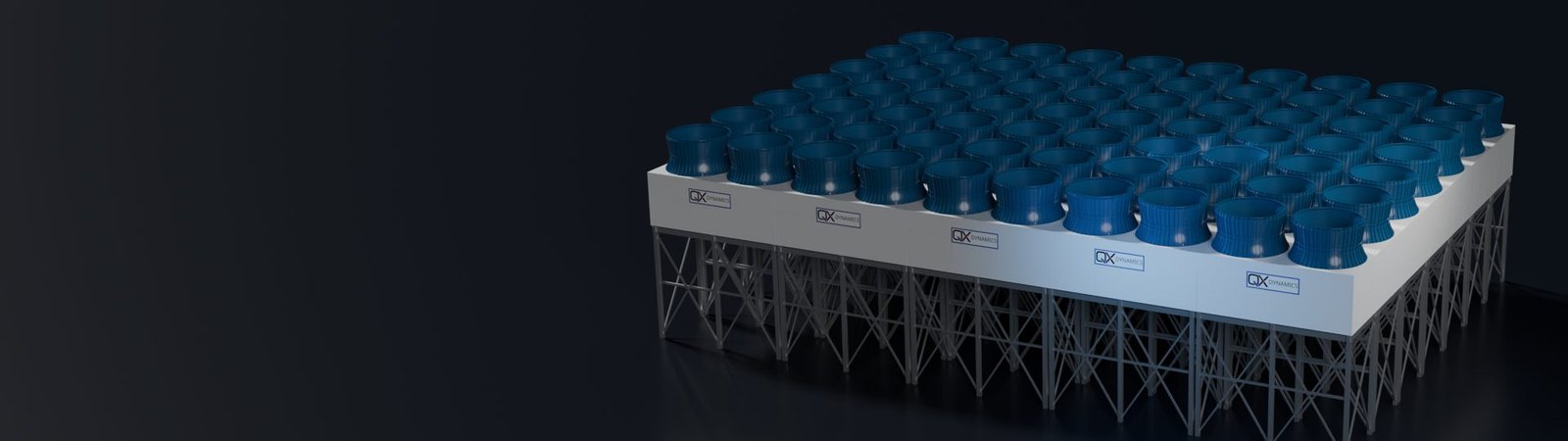
Large arrays recirculate
their own exhaust.
Put enough dry coolers side by side and the array starts pulling its own hot discharge back into the coils. Wind folds the plume over the deck, the fans draw it in, and the air entering the coil runs hotter than the weather.
An array sized as if every coil sees ambient air comes up short when that happens, and it happens on the hot, windy days the plant was sized for. More units do not fix it. A bigger yard can make it worse.
We solved it. We don't publish how. We show you the result for your site, in CFD, before you buy.
THE MECHANISM
Exhaust comes back around
Hot discharge from one part of the array is drawn into another. The larger and denser the yard, the more of it there is.
THE COST
Capacity lost on design day
Entering air above ambient means less heat rejected per unit, at exactly the conditions the array has to meet.
THE QX ANSWER
Solved, and shown on your site
We model your array, on your site, in your wind, and show you what the coils actually see.
Site engineering
One module design.
Each array engineered to its site.
A dry-cooler yard performs as a system, and the site's wind decides how well. We run full-array CFD of your layout on every project and show you the result before steel is ordered.
01
Unit count
Sized from the heat load and your design ambient.
02
Deck height
Set per site on the elevated open steel structure.
03
Spacing
Module and row arrangement within the yard you have.
04
Orientation
Rows aligned to the local wind record for the site.
| Configuration | Induced-draft (draw-through) modular dry cooler |
|---|---|
| Fans | Two large-diameter axial fans per module, in shrouded stacks |
| Fan control | Variable-frequency drive on every fan |
| Coils | Copper tubes, aluminum fins, copper headers, galvanized casing |
| Fluid | Closed loop; water or propylene-glycol mixtures |
| Structure | Field-erected on an elevated, open steel support structure |
| Service | Coil banks lower out of the casing with preplanned rigging and equipment; internal walkway to the fan deck |
| Shipping | Sections sized for standard over-the-road transport |
| Site engineering | Site-specific full-array CFD on every project |
| Finish | White steel casing and deck; blue fiberglass fan shrouds |
Talk to QX Dynamics.
Tell us about your project and we'll get back to you.